
In the Geotechnical Analysis add-on, the Hoek-Brown material model is available. The model shows linear-elastic ideal-plastic material behavior. Its nonlinear strength criterion is the most common failure criterion for stone and rocks.
You can enter the material parameters using
- Rock parameters directly, or alternatively via
- GSI classification.
Detailed information about this material model and the definition of the input in RFEM can be found in the respective chapter Hoek-Brown Model of the online manual for the Geotechnical Analysis add-on.
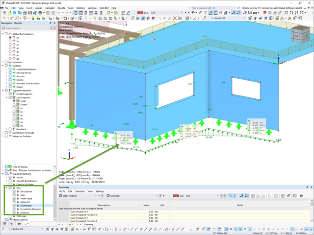
For line support results, you can optionally display certain additional information in info bubbles, such as description, sum, mean value, and so on.
If necessary, you can activate the info bubbles in the Navigator – Results.

You can open the cross-sections in RSECTION using a direct connection, modify them there, and transfer them back to RFEM/RSTAB. Both RSECTION cross-sections and library cross-sections, with the exception of elliptical, semi-elliptical and virtual joists, can be opened and modified directly in RSECTION by clicking a button.
For example, you can thus adjust the reinforcement layout of user-defined RSECTION cross-sections directly in a local RSECTION environment in RFEM/RSTAB. This feature is currently only available for cross-sections with a uniform distribution type. The shear and longitudinal reinforcement defined for library cross-sections is not imported into RSECTION.

In RFEM 6 and RSTAB 9, you can export line graphics to the SVG format (vector graphics).
SVG stands for Scalable Vector Graphics and is an XML-based file format for displaying two-dimensional vector graphics. These vector graphics can be scaled without loss. It is possible to edit the SVG files using text editors, embed them on websites, and open them in the usual browsers.

With the Concrete Design add-on, you can perform the fatigue design of members and surfaces according to EN 1992‑1‑1, Chapter 6.8.
For the fatigue design, you can optionally select two methods or design levels in the design configurations:
- Design Level 1: Simplified design according to 6.8.6 and 6.8.7(2): The simplified design is performed for frequent action combinations according to EN 1992‑1‑1, Chapter 6.8.6 (2), and EN 1990, Eq. (6.15b) with the traffic loads relevant in the serviceability state. A maximum stress range according to 6.8.6 is designed for the reinforcing steel. The concrete compressive stress is determined by means of the upper and lower allowable stress according to 6.8.7(2).
- Design Level 2: Design of damage equivalent stress acc. to 6.8.5 and 6.8.7(1) (simplified fatigue design): The design using damage equivalent stress ranges is performed for the fatigue combination according to EN 1992‑1‑1, Chapter 6.8.3, Eq. (6.69) with the specifically defined cyclic action Qfat.

The Concrete Design add-on allows you to perform the seismic design of reinforced concrete members according to EC 8. This includes, among other things, the following functionalities:
- Seismic design configurations
- Differentiation of the ductility classes DCL, DCM, DCH
- Option to transfer the behavior factor from a dynamic analysis
- Check of the limit value for the behavior factor
- Capacity design checks of "Strong column - weak beam"
- Detailing and particular rules for curvature ductility factor
- Detailing and particular rules for local ductility

The Concrete Design add-on allows you to design fiber-reinforced concrete components according to the guideline "DAfStb Steel Fiber-Reinforced Concrete".
You can use this option for the design according to EN 1992‑1‑1. The design according to the DAfStb guideline is carried out once the concrete of the "Fiber Concrete" type has been assigned to the reinforced structural component.
Go to Explanatory Video
In the "Shear Reinforcement" tab, you can select the option "Cross-ties over free rebars with active selection in graphic". It allows you to arrange additional cross-ties on free rebars of the longitudinal reinforcement.
You can activate or deactivate the position of the cross-ties in the Info Graphic. The cross-ties are applied for the ultimate limit state design and the structural design checks. They are available for the design according to EN 1992‑1‑1.
Go to Explanatory Video
When designing connections, you can now also insert a new member as a component directly in the Steel Joints add-on. This will only be considered for the connection design. You can use the Weld and Fasteners components to connect to other members.
Furthermore, it is possible to use the Member Section and Member Editor components and arrange reinforcement elements on the inserted member, such as stiffeners and tapers.
Go to Explanatory Video
In the Concrete Design add-on, you can design any RSECTION cross-section. Define the concrete cover, shear force, and longitudinal reinforcement directly in RSECTION.
After importing the reinforced RSECTION cross-section into RFEM 6 or RSTAB 9, you can use it for design in the Concrete Design add-on.
Go to Explanatory Video
A library for cross-laminated timber panels is implemented in RFEM, from which you can import the manufacturer's layer structures (for example, Binderholz, KLH, Piveteaubois, Södra, Züblin Timber, Schilliger, Stora Enso). In addition to the layer thicknesses and materials, there is also the information about stiffness reductions and the narrow side bonding.
Go to Explanatory Video
Utilize this time-saving step! This feature allows you to define or edit the member reinforcement for several members or member sets at the same time.
Go to Explanatory Video
You have the option to automatically design the existing surface reinforcement to cover the required reinforcement. You can also select whether to automatically define the reinforcement diameter or the member spacing.
Go to Explanatory Video
Complex Connection of Horizontal Beams to Column and Connection of Reinforcing Diagonals
The connection model was modeled using about 50 components. The model was created according to the real example of use in structure.
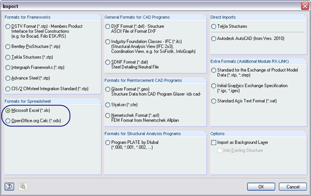
You can import table values from a prepared Excel table into RFEM 6 / RSTAB 9 with just a few clicks – either individually or all at once. For the import, you need to install a plug-in in Microsoft Excel according to this FAQ.
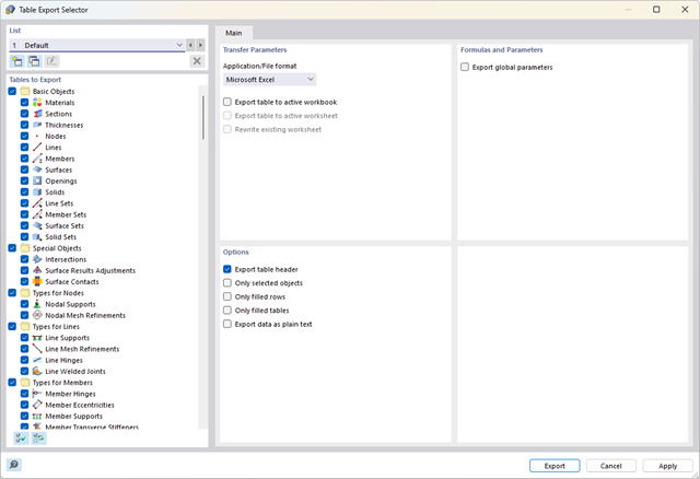
Did you know? You can export all RFEM/RSTAB tables with the results individually or all at once directly into an Excel table or as a CSV file. There are several options available to you:
- With table headers
- Selected objects only
- Filled rows only
- Only filled tables
- Export data as plain text
This way, the program allows you to control and clearly manage the exported data. You can export the stored formulas directly in the table or as a separate table, as in the case of the used parameters.

Do you prefer it clear? So do we! That's why all performed design checks for the design standard are displayed for you in a clear way. You determine a design criterion for each design check. You get design details, which include the initial values, intermediate results, and final results, arranged in a structured way for each design check. You can find the calculation process with the applied formulas, standard sources, and results in great detail in an information window in the design details.
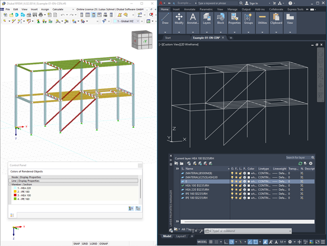
Use the interfaces for more efficient work. You can import your structures in the DXF format as lines from Autodesk AutoCAD into RFEM 6 / RSTAB 9.
Furthermore, you can export different objects (for example, cross-sections) from RFEM 6 / RSTAB 9 to separate layers in Autodesk AutoCAD.

The object types listed below can be graphically assigned to the elements of the structure modeled in the program.
- Nodal supports
- Member shear panels
- Local reductions of member cross-sections
- Member transverse stiffeners
- Member longitudinal welds
- Effective lengths
- Boundary conditions
- Line supports
- Loads
- Member support
- Punching reinforcements
- Mesh refinements
- Surface reinforcements
- Surface results adjustments
- Surface support
- Service classes
- Imperfections

RFEM allows you to use a special line hinge to model the special properties of the connection between the reinforced concrete slab and masonry wall. This limits the transferable forces of the connection depending on the specified geometry. You guess right: This means that the material cannot be overloaded.
The program develops interaction diagrams that are applied automatically. They represent the various geometric situations and you can use them to determine the correct stiffness.

- Design of tension, compression, bending, shear, torsion, and combined internal forces
- Consideration of a notch
- Design of compression perpendicular to the grain on the end and intermediate supports with (EC 5) and without reinforcement elements (fully threaded screws)
- Optional shear force reduction at the support (see the Product Feature)
- Design of curved and tapered members
- Consideration of higher strengths for similar components that are close together (factor ksys according to EN 1995‑1‑1, 6.6(1)-(3))
- Option to increase shear resistance for softwood timber according to DIN EN 1995‑1‑1:NA NDP to 6.1.7(2)

RFEM/RSTAB also provides a range of functions for the case of a fire. The program allows for the automatic generation of load and result combinations for the accidental design situation of fire design. The members to be designed with the corresponding internal forces are imported directly from RFEM/RSTAB. Also, all information about the material and cross-section is stored. You don't need to do anything else.
You only define the parameters relevant for the fire resistance design by assigning a fire resistance configuration to the members and surfaces to be designed. Moreover, you can also make further detailed settings, such as the definition of the fire exposure on one side up to all sides.

Dlubal Software just makes everything a little easier. The performed design checks of the design standard are displayed in a clear way. A design criterion is determined for each design check. Furthermore, the program deliver the design details displayed in a structured way, including the initial values, the intermediate results, and the final results. An information window in the design details shows you the calculation process with the applied formulas, standard sources, and results in great detail.

The structural analysis programs RFEM/RSTAB offer you a wide range of automated functions that make your dayily work easier. One of them is the automatic generation of load and result combinations for the accidental design situation of fire design. The members to be designed with the corresponding internal forces are imported directly from RFEM/RSTAB. You don't need to do anything else. The program has also already stored all information about the material and cross-section for you.
By assigning a fire resistance configuration to the members to be designed, you define the parameters relevant for the fire resistance design. Here you can manually specify the critical steel temperature at the design time. Or let the program to determine the temperature determined automatically for a specified fire duration. You can select from various fire temperature curves and fire protection measures. It is also possible to make further detailed settings, such as the definition of the fire exposure on all sides or three sides

Is a clear arrangement important for you? The program provides you with a clear overview of all performed design checks for the design standard. For each design check, it is necessary to determine a design criterion. There are also design details arranged in a structured way, including the initial values, intermediate results, and final results. You can laso find here an information window where the calculation process with the applied formulas, standard sources, and results is displayed in great detail.
.png?mw=640&hash=342149908caead326e60e26a2b5d05f7f46825cb)
Are you familiar with the Tsai-Wu material model? It combines plastic and orthotropic properties, which allows for special modeling of materials with anisotropic characteristics, such as fiber-reinforced plastics or timber.
If the material is plastified, the stresses remain constant. The redistribution is carried out according to the stiffnesses available in the individual directions. The elastic area corresponds to the Orthotropic | Linear Elastic (Solids) material model. For the plastic area, the yielding according to Tsai-Wu applies:
All strengths are defined positively. You can imagine the stress criterion as an elliptical surface within a six-dimensional space of stresses. If one of the three stress components is applied as a constant value, the surface can be projected onto a three-dimensional stress space.
If the value for fy(σ), according to the Tsai-Wu equation, plane stress condition, is smaller than 1, the stresses are in the elastic zone. The plastic area is reached as soon as fy (σ) = 1; values greater than 1 are not allowed. The model behavior is ideal-plastic, which means there is no stiffening.

Did you know? In contrast to other material models, the stress-strain diagram for this material model is not antimetric to the origin. You can use this material model to simulate the behavior of steel fiber-reinforced concrete, for example. Find detailed information about modeling steel fiber-reinforced concrete in the technical article about Determining the material properties of steel-fiber-reinforced concrete.
In this material model, the isotropic stiffness is reduced with a scalar damage parameter. This damage parameter is determined from the stress curve defined in the Diagram. The direction of the principal stresses is not taken into account. Rather, the damage occurs in the direction of the equivalent strain, which also covers the third direction perpendicular to the plane. The tension and compression area of the stress tensor is treated separately. In this case, different damage parameters apply.
The "Reference element size" controls how the strain in the crack area is scaled to the length of the element. With the default value zero, no scaling is performed. Thus, the material behavior of the steel fiber concrete is modeled realistically.
Find more information about the theoretical background of the "Isotropic Damage" material model in the technical article describing the Nonlinear Material Model Damage.

Stay informed with our Knowledge Base: Here you can find useful technical articles about the "Structural Analysis and Design" that will support you in your daily work. You will also get useful tips & tricks for the correct and efficient application of the Dlubal structural analysis programs.
KNOWLEDGE BASE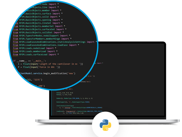
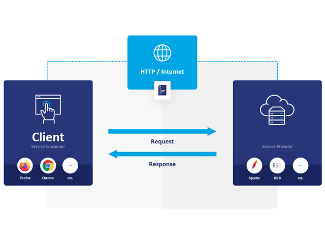
One thing is absolutely undisputed: WebService and API covers universal aspects in the construction industry. However, there is an issue. For the calculation and design, you need different features for each region, country, company, and civil engineer. Everyone has their own requirements. We have solved this problem. Since with WebService and API, you can easily create your very own calculation and design system. Always at your side: The performance and reliability of RFEM, RSTAB, and RSECTION.
The need for adapted and automated structural analysis and design is constantly increasing. WebService technology allows you to create special functionalities quickly and precisely. Our customers can develop such solutions independently or in cooperation with us. See for yourself and give it a try!
WebService and API provide you various scope of application. We have summarized some ideas as to how WebService and API can support your company:
- Creating additional applications for RFEM 6, RSTAB 9, and RSECTION 1
- Possibility to make the workflows more efficient (for example, model definition and input) and to integrate RFEM 6, RSTAB 9, and RSECTION 1 into your company applications
- Simulating and calculating several design options
- Running optimization algorithms for size, shape, and/or topology
- Accessing the calculation results
- Generation of printout reports in the PDF format
The level of quality of the work is automatically increased not only by the algorithmic model definitions, but also by:
- Extending / consolidating RFEM 6, RSTAB 9, and RSECTION 1 with your own controls
- Increased interoperability between the individual software used to complete a project